When designing medium, high or extra high voltage installations, special care must be taken when considering the protection of people who work and transit through these facilities. This is why the design of the grounding system is of special interest given the complexity it represents. Just as important as design is the verification of theoretical design results after execution
Earthing system designs are made based on international standards, recommendations or local regulations. IEEE 80 standards (Guide for Safety in AC Substation Grounding) give us a design criterion. IEC in its regulations gives us a design guide in EN 50522 but in particular IEC 60479 (Effects of current on human beings and livestock) explain the effects that occur when circulating current through the body, in its part 5 it speaks of contact voltage. Whatever design method used, the result must be verified once implemented by making measurements and for this the standards IEEE 81, EN 50522, IEC 60479 detail how to make such measurement.
In addition, other factors require special attention such as the behavior of the grounding system under study with reference to other interconnected grounding, as is the case with substations that are interconnected by guard wire with energy towers which are earthed locally.
The old measurement methods for substations required high currents for which a generator had to be placed on site, the work area cleared and measurements made, which implied an additional risk. It also represents a challenge to measure so that it is not affected by noise or disturbances. The standard shows some methods that were intended to be used to avoid this. Current regulations allow the use of intelligent instruments for such measurement without the need of injecting large currents generating risky conditions. Our instruments allow measurement ensuring that rods used will not receive more than 55 volts using a highly sensitive voltmeter with filtration to achieve measurement in the most demanding conditions
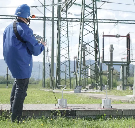
The MI3295 instrumet is a proven device with years of experience in different applications. It includes the possibility of measuring specific resistance (or resistivity), resistance of ground mesh but also the step and touch voltage. By generating signal at 55 Hz, this is injected to simulate failure condition and by using the fall of potential method with a remote installed rod, user can move safely within the area being analyzed to, through a portable instrument, perform measurements.
Measurement using MI3295
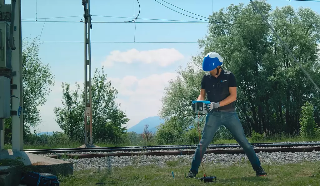
MI3290 on the other hand comes in four versions such that users can scale instrument according to their needs. It can perform measurement of specific grounding (resistivity) by Wenner and Schlumberger methods, grounding by means of 2, 3 or 4 rods, selective grounding by means of one clamp, grounding by means of two clamps without disconnection of earthing system. It adds high frequency method up to 25 kHz according to IEEE 81 being able to select fixed frequency or frequency sweep. This is especially useful for analyzing behavior in transients or for measuring ensuring independance of remote earthings interconnecte (classic example is substation linked by guard wire to remote grounding of each tower). Depending on instrument chosen version, you can also measure energy towers earthing with one to four supports (varies number of flexible current clamps and can even perform measurements interconnecting flexible clamps achieving up to 10 meters of extension for measurement if other geometrical shape). This system calculates the current partition factor and gives the grounding status of each support separately. Additionally, it can allow current measurement or act as a small micro ohmmeter for primary status verification. It also can include the 10/350 μA waveform test for transients of the atmospheric impulse type to allow verification of lightning rod grounding systems or behavior of grounding systems in the event of such an event. It can also perform the step and touch voltages measurement to verify the safety of the system.
Measuring energy towers
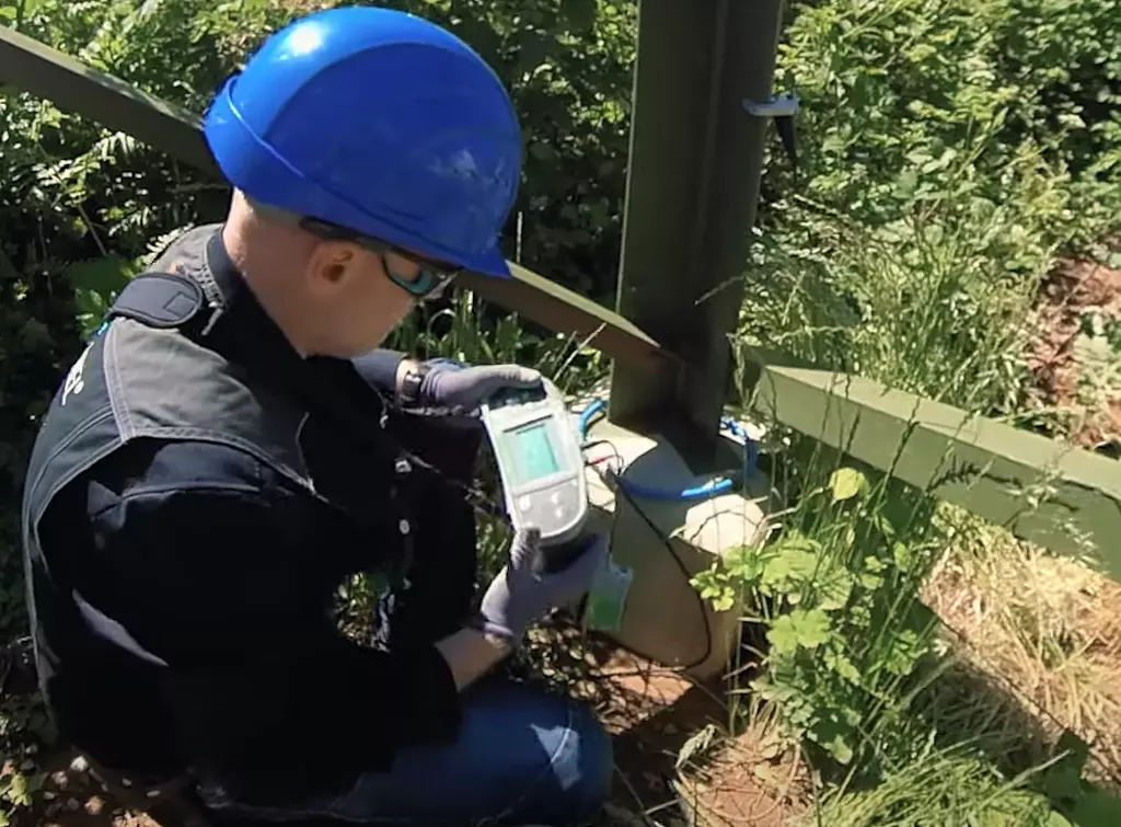
For those who need besides measuring grounding, to verify the continuity of the protection conductors either of electrical systems, communication antennas or others, MI3288 is the instrument to consider. This model can measure in addition to specific ground resistance by Wenner and Schlumberger methods, 4-pole grounding resistance, selective grounding with one clamp or by two clamps, ground potential, step and contact voltage but adds insulation resistance up to 2500 volts (including DAR and PI) and continuity of ground conductors. It even allows you to measure TRMS current, useful when you are in the field or even verify the breakdown voltage or actuation condition in surge protection equipment (varistors for example) up to 2.5 kV. In addition to micro ohmmeter for primary indications of connection status (limited injection of current not being a specific equipment of high current that exist in the offer)
Step voltage using MI3288
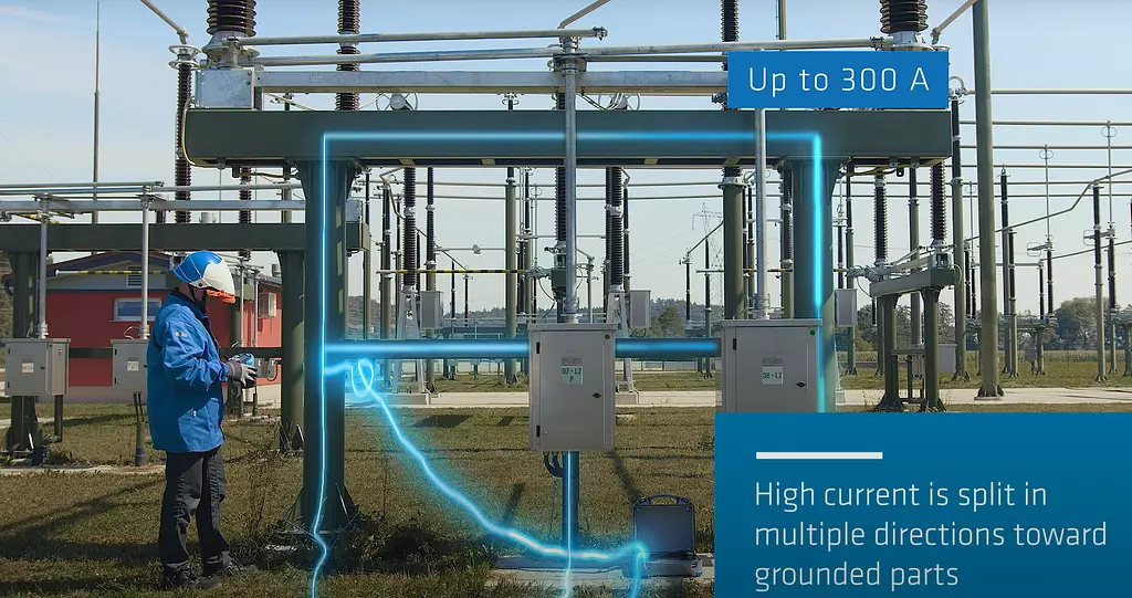
If what you want is to measure the integrity of the grounding system (IEEE 81 Integrity of Grounding Systems according to 10.2, 10.3) then MI3144 allows tests with up to 300 Amps to verify the status of the earthing system. By measuring current using the flexible clamp (Rogowski) connected to it and using Android application (bluetooth) you can perform measurement (or using another instrument for command)