In order to avoid electrocution (or in other words, to avoid the occurrence of ventricular defibrillation) as well as to prevent fires in electrical installations in the event of a ground fault, it is advisable to install residual current protection devices. There are automatic RCB switches on the market that integrate the magneto-thermal and RCB in one device, automatic RCB switches that only fulfill the residual current function, RCBl switches that act on trip coils of protection devices, among several others. Also, they are offered with different sensitivities (10 mA, 30 mA, 100 mA, etc.) to allow selectivity and also with different trip times. There are currently also the so-called super immunized (or delayed) RCBs to avoid tripping due to leakage (common in equipment with sources such as PCs, among others)
A separate chapter is the type of residual current device to use according to the composition of the quality of electrical energy in the installation where it will be used. The IEC 60755 standard defines four types. AC types are designed for general use on sinusoidal residual waveforms. Type A add to type AC the ability to detect pulsating DC residual current (maximum 6 mA). Such waveforms can be caused for example by a diode or thyristor rectifier circuit in electronic loads. There are the type F have recently been introduced in the standards IEC 62423 and IEC60755. These, in addition to the detection characteristics of type A devices, type F are specially designed for the protection of circuits in which single-phase variable speed drives can be used, elements that are increasingly used for reasons of energy efficiency. In these circuits, the residual current waveform could be a combination of multiple frequencies, including motor frequency, converter switching frequency, and line frequency. Type F does not trip on overcurrent and can trip even if a pure direct current of 10mA is superimposed on a sinusoidal or pulsed dc differential current. Finally, type B is defined, which can detect sinusoidal ac, pulsating dc, multifrequency, as well as uniform DC residual currents. Also, the trigger conditions are defined with different frequencies from 50 Hz to 1 kHz. In an ac electrical distribution network, a pure dc residual current can be generated mainly from three-phase rectifier circuits, but also from some specific single-phase rectifiers. Type B differentials are intended for loads with a three-phase rectifier, such as variable speed drives, photovoltaic systems, electric vehicle charging stations and medical equipment.
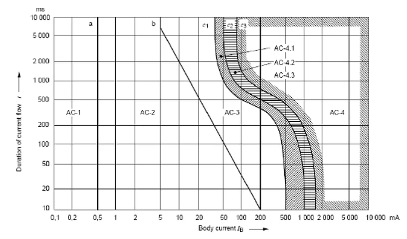
To avoid electric shock, the limit value is 30 mA. This arises from the recommendation of the IEC 60479-1 standard as shown in the figure. That standard shows earth fault current curves per body depending on the fault time, classifying the areas according to the effect. To avoid irreversible effects we must make sure we are at least in the AC3 zone and this is achieved with a residual current protection that, in the worst case, acts at 30 mA
Current effects as per IEC 60479-1
Such standard establishes that the impedance of the body when failure occurs in a dry environment for 95% of the population is 1700 ohms. This implies that in a 230 Vac network the maximum allowed touch voltage is 50 V (Ohm's law knowing the differential current is 30 mA and the body impedance 1700 ohms), changing the value for a humid environment to 24 V. This is so for fundamental frequency and different curves are presented for higher frequencies. These values are part of those requested by local installation regulations in different countries.
It is important to mention that the residual current devices not only fulfills the function of protection of the person but of protection of the installation. Studies have shown that leakage currents as low as 300 milliamps can cause a fire. A contaminated insulation surface in a humid environment can cause small electrical discharges that cause charring. This environment causes an increase in conductivity. In this condition, the carbon deposits and the insulation can ignite and therefore cause a fire.
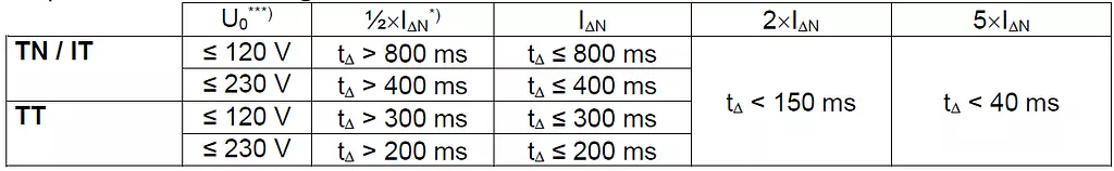
But it is important to understand then that when we talk about residual current protection we are referring to a device that has a tripping curve and do not trip on a fix value. This curve admits a maximum value, for example 30 mA, in a given time. Standard IEC 60364 refers to installations in buildings and in its part 4 (protection against electric shocks) mentions that domestic residual current devices will act as the worst condition in 30 mA and 40 ms (milliseconds). It establishes test values according to the type of neutral grounding (TN, TT or IT network) as we can see below
tripping values as per IEC 3064-4-41
Also such values for residual current devices are described on IEC 61008 (Residual current operated circuit breakers without integral overcurrent protection for household and similar uses) and 61009 (Residual current operated circuit breakers with integral overcurrent protection for household and similar uses)
Tripping values as per IEC 61008 y 61009
Residual current protection devices must be tested periodically to verify that they continue to meet the design conditions and therefore the installation continues to be safe. To test them, the IEC 61557-6 standard establishes maximum trip times, for example for instantaneous and time delayed RCBs for general use.
Instantaneous RCBs
Time delayed RCBs
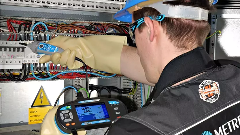
It is clear then it is of vital importance, both for people and for installation safety, that residual current protection devices are tested. As with any electronic element, RCDs are prone to failures, to breakdown or to act outside of its design condition. Therefore they MUST BE TESTED periodically. To achieve this, we have several testers that allow selecting the type of RCD, the standard to be used for testing pursposes and allows carrying out the test automatically. The instrument must at least allow measurement of trip time, trip current, touch voltage (to verify safe installation condition) and allow automated testing at all points of the standard curve (different currents verifying trip times and recording them). Some tests are carried out with low current values (below half of the actuation current) such that it is possible to carry out the measurement without tripping the RCD, ensuring continuity of service and verification at the same time. To test the tripping current, the increase of injected current will be according to the type of RCD being tested using a sinusoidal, pulsed or dc waveform, as appropriate. The automatic test implies injection of current with different phase angles and different current values, the device will trip in some cases and do not trip in others. The entire procedure is recorded and saved.
MMetrel offers a complete range of testing instruments that allow multiple tests, in particular RCD testing. We invite you to get in touch as we have an instrument for every need